Wind Turbine Project
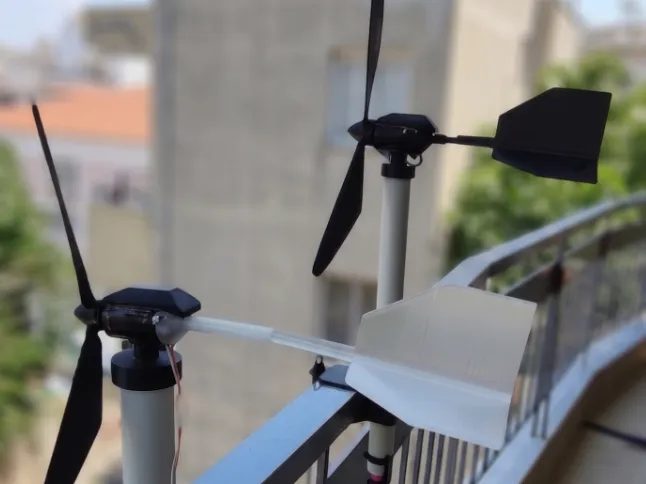
A 3D-printed balcony turbine that turns wind into charge for an 18650 battery. This guide covers the circuit, the perfboard layout, the soldering order and how the printed parts go together.
How it works
The blades spin a small DC motor, which then works as a generator. Its voltage goes up and down with the wind, so it passes through four stages before it reaches the battery.
Illustrative simulation to show the behaviour, not measured data. Real voltages depend on your motor and the wind.
1 · Motor as generator
Spinning a brushed DC motor makes a DC voltage that rises with speed. If a gust pushes the rotor backwards, the polarity flips. Tick “Rotor spins backwards” to see it.
2 · Bridge rectifier
Four diodes make the output positive whichever way the motor turns, so the turbine wires can go either way round. Each pass costs two diode drops.
3 · Capacitor
A large electrolytic smooths gusts and the motor’s brush ripple, and gives the boost converter a short reserve to start from.
4 · MT3608 boost
Turns anything above about 2 V into a steady 5 V. Below that it does not start, which is why light wind gives no charge.
5 · TP4056 charger
Charges the 18650 to 4.2 V and protects it from overcharge, overdischarge and short circuit. Red LED is charging, blue is full.
Parts list
For one charging box with two turbines. For a single turbine, halve the diodes, use one MT3608 and leave input B empty.
| Part | Qty | Job | Notes |
|---|---|---|---|
| MT3608 boost module HW-045 | 2 | Raises the turbine voltage to 5 V | One per turbine. The blue trimmer sets the output voltage. |
| TP4056 charger with protection 03962A | 1 | Charges and protects the 18650 | Buy the 6-pad version with B+ B− and OUT+ OUT−. The 4-pad version has no protection. |
| Rectifier diode, 3 A 1N5408 size | 8 | Two bridge rectifiers | 4 per turbine. The original uses large DO-201 silicon diodes. 1N5822 Schottky diodes work better (see Upgrades). |
| Electrolytic capacitor | 1–2 | Smooths the rectified voltage | The original has one large can. Its value isn’t readable in the photos; 1000 µF at 16 V or higher works. |
| 18650 Li-ion cell + single holder with leads | 1 | Energy storage | Use a real, branded cell. Holder leads: red +, black −. |
| Perfboard | 1 | Carries everything | The original is about 4 × 9 cm, single-sided, 2.54 mm pitch. |
| 2-pin connectors Dupont / JST | 3 | Turbine A, turbine B, battery | Lets you unplug the turbines and the battery. |
| Male header pins | ~12 | Mount the modules | The modules stand on pins soldered into the perfboard. |
| Small brushed DC motor (2 wires) | 1 per turbine | The generator | Must fit the nacelle housing. Measure the bore in your slicer before buying. |
| 2-core wire, hook-up wire, heat-shrink | — | Turbine leads and on-board links | Leave enough length to reach from the turbine head down to the box. |
Schematic
Two identical input channels feed one charger. Each MT3608 has its own output diode inside, so the two outputs can be joined directly.
B− and OUT−/IN−. Connect only the battery to B+/B−, and never join B− to any other negative wire, or the protection stops working.The board
Left: the original build, numbered. Right: the same layout drawn out, with the connections from the schematic. Tap a wire group to highlight it.
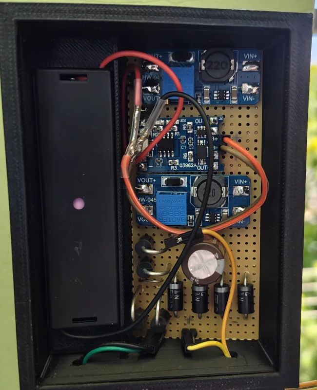
The original uses insulated jumper wires and solder bridges on the back, which aren’t visible in the photos. This drawing keeps the original placement and wires it exactly as the schematic.
Wiring the bridge rectifier
This is where most mistakes happen. Build one bridge per turbine.
The rule: every stripe faces the + rail. The stripe marks the cathode. Make two legs, each with two diodes in series, both stripes pointing up toward +.
Motor wires go to the middle of each leg, one wire per leg. Polarity doesn’t matter here.
The + rail (where two stripes meet) goes to the capacitor’s + leg and to VIN+ on the MT3608.
The − rail (where two plain ends meet) goes to the capacitor’s stripe (−) and to VIN−.
In the original, bridge A stands in a row at the bottom right with every stripe at the top, and bridge B is four diodes standing on end at the bottom left.
Soldering, step by step
Do the steps in this order. Each one ends with a quick check so a mistake can’t hide until the end.
Set both MT3608 modules to 5.0 V before soldering anything
Power each module’s
VIN+/VIN−from 3.7–5 V (a USB lead or the 18650 itself). MeasureVOUTand turn the brass screw on the blue trimmer until you read 5.0 V. It can take 10–20 turns before anything changes.New modules often arrive set to 12–28 V. The TP4056 is damaged above 8 V, so never connect a boost to the charger before setting it.VOUT = 4.9 – 5.2 V on both modulesMount the three modules
Solder header pins into the module pads, then into the perfboard. From the top: boost B, the TP4056 with its USB socket at the left edge so you can still reach it, then boost A. On both boosts the
No pins bridged; modules sit flatVOUTpads face left andVINpads face right, as in the photo.Build bridge A and capacitor C1
Four diodes in the lower right, stripes toward +, wired as in section 05. Put C1 across the + and − rails, stripe side to −.
Spin turbine A by hand: rails read positive both waysBuild bridge B
Same circuit in the lower left. The original fits it in by standing the diodes on end. A second capacitor here is a good addition.
Same test with turbine BConnect each bridge to its boost
Bridge A + rail to boost A
Spin hard: boost output jumps to 5.0 VVIN+, − rail toVIN−. Bridge B to boost B the same way.Join the outputs to the charger
Both
With a turbine spinning, IN+ to IN− = 5 VVOUT+pads to TP4056IN+. BothVOUT−pads toIN−. Keep these wires short, along the left edge.Add the input connectors
Two 2-pin connectors on the bottom edge, wired to the middle points of each bridge. J1 (turbine A) is the centre one, J2 (turbine B) is on the left.
Connect the battery last
A 2-pin plug on the TP4056
B+/B−pads. Holder red lead toB+, black toB−. Check the polarity twice before inserting the cell. Cover every splice with heat-shrink.Reversed battery = dead charger, and possibly a hot cell. The TP4056 has no reverse-polarity protection.B+ to B− reads 3.0 – 4.2 V with the cell inFit it in the box
Battery holder on the left, board on the right, turbine leads out through the slots in the bottom.
OUT+/OUT−stay free; that’s where a load such as a USB booster or a light can take power from the battery later.
Assembling the turbine
Same order as the exploded view in the model files. Play it, or step through it part by part.
Motor into the housing
Wire routing
Lead the two motor wires out under the nacelle and down beside the pole, as in the photos. Leave a loose loop at the top so the head can turn with the wind without pulling on the solder joints.
Blade balance
Weigh the three blades and sand the heaviest one until they match. An unbalanced rotor shakes, wastes energy and loosens the hub.
Mounting
The base clamps to a railing or post; the pin with the ring locks it. The originals also have a strap around the pole for extra hold in strong wind.
Testing and troubleshooting
Test on the bench with a cordless drill spinning the hub (gently, at low speed) before going outside.
| What you see | Likely cause | Fix |
|---|---|---|
| Nothing happens in light wind | Below about 2 V after the bridge, the MT3608 doesn’t start | Normal. Schottky diodes or a higher-voltage motor lower the threshold. |
| Red LED flickers on and off | The charger asks for more current than the turbine can give, the voltage sags, it restarts | Normal in gusty wind. Lower the charge current to make it steadier (Upgrades). |
| Boost output reads 0 V either way | A diode in the bridge is reversed, or VIN+/VIN− swapped | Recheck that every stripe faces the + rail. |
| Boost output is far above 5 V | Trimmer not set | Disconnect from the TP4056 and set it to 5.0 V first. |
| LEDs on but battery voltage doesn’t rise | Battery wired to OUT+/OUT− instead of B+/B− | Move the battery plug to B+/B−. |
| Blue LED stays on, cell isn’t full | Cell not connected, or holder springs not touching | Measure at B+/B− with the cell in. |
| MT3608 gets hot | Output shorted or charger drawing 1 A from a weak input | Check for bridges; lower the charge current. |
Optional upgrades
Not in the original build, but each one helps a small turbine.
Schottky diodes
Swap the 1N5408s for 1N5822. A silicon diode drops about 0.9 V, a Schottky about 0.4 V. Two sit in the path, so the turbine starts charging about 1 V sooner. Try it in the simulation above.
Lower charge current
The resistor marked R3 (printed “122”, 1.2 kΩ) sets 1 A of charge current, far more than a small turbine makes. Replacing it with 4.7 kΩ (about 250 mA) or 10 kΩ (about 130 mA) gives steadier charging.
Second capacitor
Add 1000 µF across bridge B as well, so both channels behave the same.
Outdoor plastic
PLA softens in summer sun on a balcony. PETG or ASA keep the blades and hub in shape.
Keep the box cool and dry
Li-ion cells shouldn’t charge above about 45 °C. Mount the box in shade and keep rain off the open front.
Use the stored energy
Connect a second MT3608 set to 5 V, or a small USB booster, to OUT+/OUT− to charge a phone or run a light from the battery.